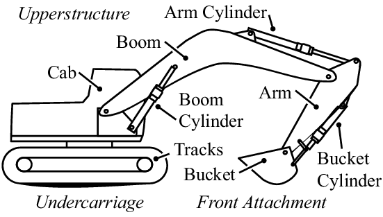
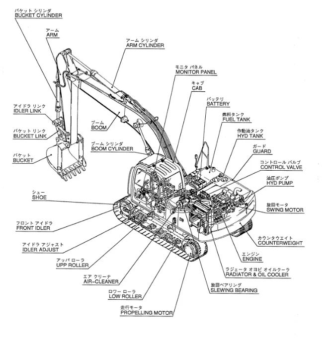
An excavator is a versatile piece of heavy equipment commonly used in construction, mining, and landscaping projects. Understanding the components and functions of an excavator machine diagram is essential for operators, technicians, and enthusiasts to grasp the intricate workings of this powerful machine. Let’s delve into the key components of an excavator machine diagram:
| Component | Function |
|---|---|
| 1. Cabin | – Houses the operator and controls the excavator’s functions. |
| 2. Engine | – Provides power to drive the hydraulic system and move the machine. |
| 3. Hydraulic System | – Powers the movement of the boom, arm, bucket, and other attachments. |
| 4. Boom | – Long, vertical arm that extends from the machine’s body and provides reach and height. |
| 5. Arm | – Attached to the end of the boom, works with the boom for digging, lifting, and reaching. |
| 6. Bucket | – Scoops, lifts, and dumps materials, available in various sizes for different tasks. |
| 7. Tracks/Wheels | – Provide stability and mobility to the excavator, allowing movement across various terrains. |
| 8. Undercarriage | – Supports the weight of the machine and includes tracks, rollers, idlers, and sprockets. |
By understanding the excavator machine diagram and the functions of each component, operators can effectively operate the machine, perform tasks efficiently, and ensure safety on the job site. Proper maintenance, regular inspections, and adherence to operational guidelines are crucial for maximizing the performance and longevity of excavators in demanding work environments. Each component in the excavator machine diagram plays a vital role in the overall functionality of the machine, making it an indispensable tool for a wide range of construction and excavation projects.