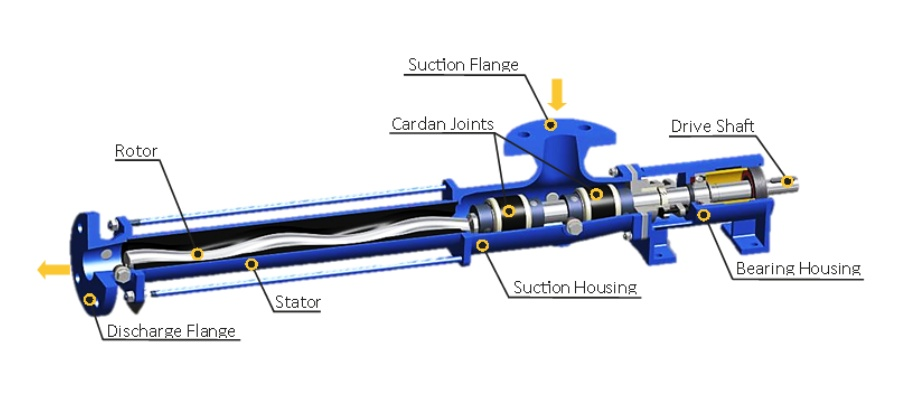
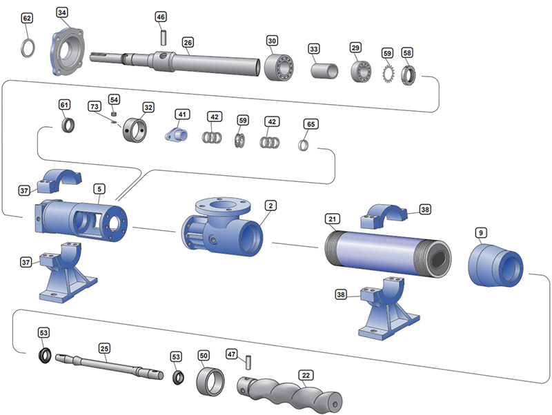
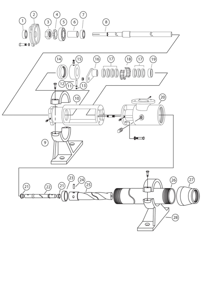
Moyno pumps are widely recognized for their reliability and efficiency in handling viscous and abrasive fluids. To properly maintain and troubleshoot these pumps, having a clear understanding of the Moyno pump diagram is essential. This diagram illustrates the various components and their interconnections, providing a visual guide to the pump’s operation.
At the heart of the Moyno pump is the rotor, which plays a crucial role in fluid movement. The diagram typically shows how the rotor rotates within the stator, creating a series of cavities that transport liquid from the suction side to the discharge side. Understanding this relationship is vital for diagnosing performance issues; for instance, if the rotor or stator wears down, it can lead to reduced efficiency and flow rates.
The suction and discharge ports are prominently featured in the diagram. These ports indicate where the fluid enters and exits the pump. Maintaining these connections is crucial for ensuring optimal performance. Blockages or leaks at these points can significantly hinder pump operation, making it important to refer to the diagram when conducting inspections or repairs.
The bearings and seals are also important components depicted in the Moyno pump diagram. Bearings help support the rotor and reduce friction during operation, while seals prevent leakage and maintain pressure within the system. A clear understanding of how these parts fit into the overall design helps technicians identify potential problem areas during maintenance.
Another critical element often shown in the diagram is the drive unit, which powers the rotor. This unit can be electric or hydraulic, depending on the application. Familiarity with the drive unit’s placement and connections is key to troubleshooting any operational issues.
In conclusion, the Moyno pump diagram serves as an invaluable tool for anyone working with these pumps. It provides a comprehensive view of the various components and their functions, aiding in maintenance, troubleshooting, and repair. Understanding this diagram ensures that operators can effectively monitor the pump’s performance and promptly address any issues, ultimately leading to enhanced efficiency and longevity of the pump. Regular reference to the diagram will empower technicians to make informed decisions that keep operations running smoothly.